PowerBook Duo 230 repair

By Lucas/11th May 2020/Comments are closed
Introdution
This lovely, small fellow has been brought by one of our customers after some failed repair at one of Birmingham’s computer shops. Manufactured in 1992, it was working perfectly fine until a small liquid has been spilled on the keyboard and partially on the trackball.

Step 1 – Diagnostics
Computer was starting up with chime, however, there was no picture on the screen and no HDD noise. Customer stated that after an accidental spillage he could hear the chime and noise of a spinning HDD (this model does have a very capacious 120MB IBM drive). Unfortunately, the previous repair company gave up on this repair after over 4 months, so first of all we opened it to see what had been done by the previous company. We quickly discovered that there is still a residue of some substance on the logic board (how could that be overlooked?):
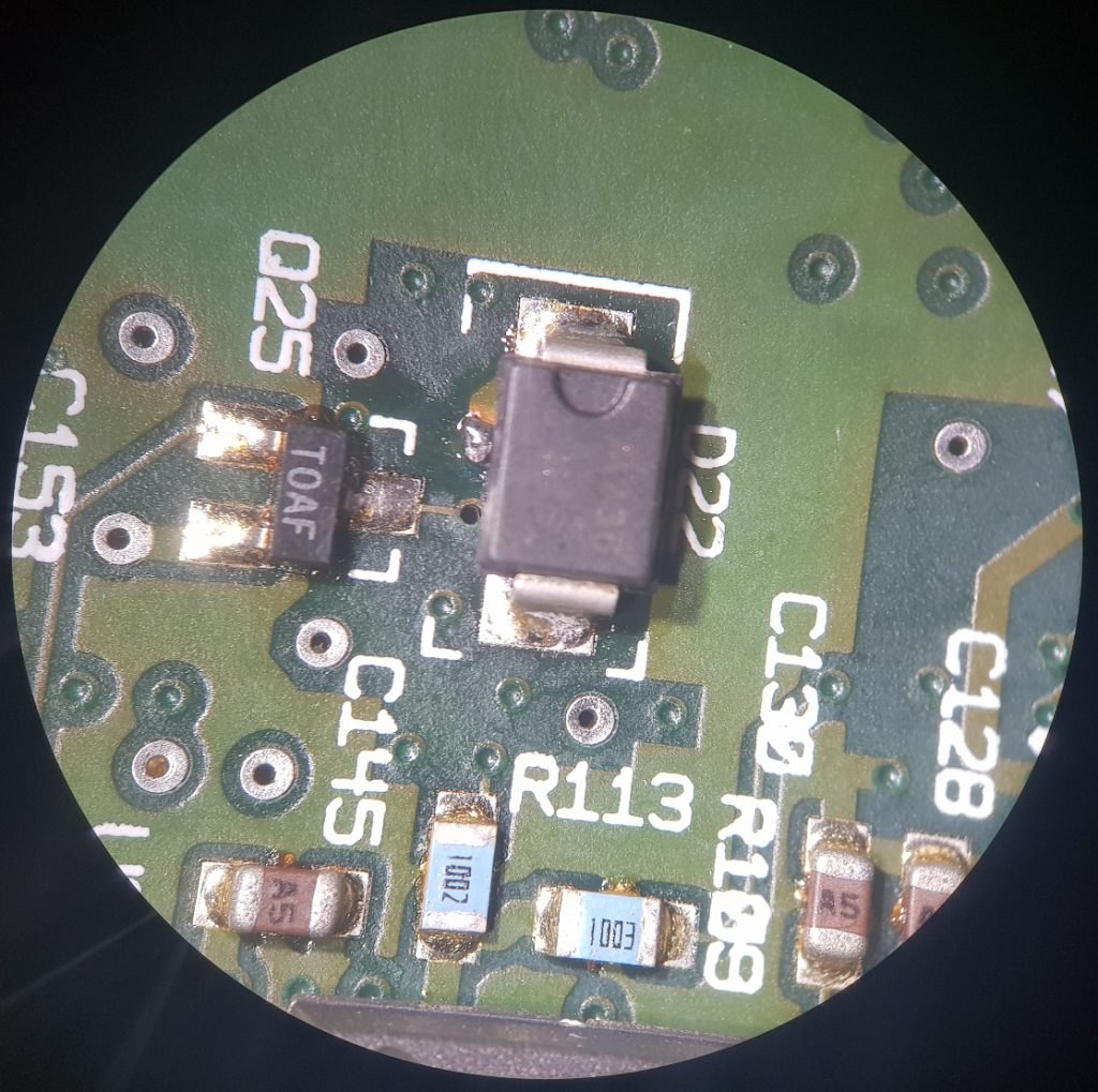
We cleaned a whole logic board to prevent from further corrosion spreading. Unfortunately, after reassembling, the computer was still not willing to cooperate. Logic board had been pulled out again and examined carefully under the microscope (especially the area which had a liquid residue), and we quickly discovered something suspicious – one of the vias was looking slightly different than others:
We checked with the schematic diagram that this via connects pin 3 (source) of Q7, dual P-Channel MOSFET (IRF9953), with a cathode of D22 (10BQ100T), which provides 5V for the logic circuit and… for the HDD. Measurement of continuity has uncovered that there is no electrical connection between cathode of D22 and pin 3 of Q7. That was a turning point of our diagnostics – we have restored that broken via to get the proper 5V voltage on pins 5 and 6 (drain) of Q7.
Step 2 – Repair process
We removed a soldermask from the surrounding area of broken via (both sides) and put a silver-plated wire into the hole.

Then we were able solder the wire to restore an electrical connection between both sides of PCB. We had to move D22 diode slightly away of that via.


After restoring that broken connection, we moved D22 diode back in place:
Step 3 – Tests
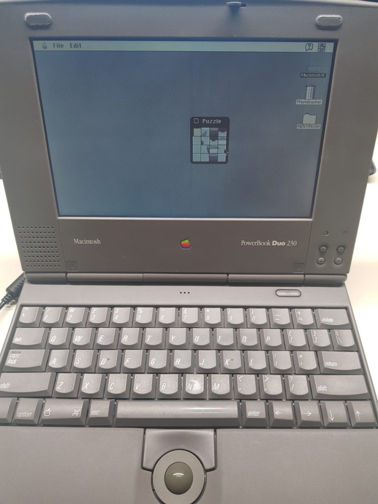
The logic board had been connected to our bench power supply and we realised that it takes more current than before the repair. That was a good sign so we decided to reassemble the computer – it started up, loaded the operating system and we could watch this beautiful piece of electronics back in action!
Summary
It is always worth to examine the logic board under a microscope – especially if the computer had been liquid spilled. All signs of corrosion can be easily found if you do not attempt to limit the time of a visual inspection.
16 Comments
Comments are closed.
watch says:
30th January 2021 at 9:09 am
Some really nice and useful info on this website, as well the style and design has got excellent features. Pammi Chucho Thapa
Lucas says:
12th February 2021 at 11:01 pm
… and there will be more of it soon!
richardcaple says:
8th February 2021 at 5:39 am
You actually make it seem really easy along with your presentation but I’m finding this topic to be actually one thing which I think I’d never understand. It seems too complicated and very extensive for me. I’m looking forward to your subsequent submit, I’ll attempt to get the hold of it!
Lucas says:
12th February 2021 at 10:59 pm
It indeed IS really easy as long as you want to learn 🙂
Steven Hoefel says:
12th February 2021 at 12:26 pm
Hi elvikom,
On the logic board of this PowerBook are two AT&T branded inductors/chokes/coils/transformers. Can you tell me what they actually are? I need a replacement for the left-hand “152-0012” and I can’t find any information anywhere!
Steven.
Lucas says:
13th February 2021 at 1:27 am
Hi Steve 🙂 Both L5 and T1 are actually transformers. L5’s part number is 152-0012 and T1’s one is 157-0134. Both of those are designed and manufactured for Apple and they are not available for purchase. If you need one, you may be forced to buy an 820-0426-D logic board to source these parts. However, as long as the ferrite core is not damaged, you can make such transformer by yourself – all you need is to measure the diameter and length of all wires. Please note that 152-0012 transformer has a more complicated coil winding connections than 157-0134 (which has 4 identical and separate windings). Here is the part of schematic diagram I drawn from the logic board some time ago to get this circuit more clear and understandable, you can also see the connections inside both transformers: https://www.elvikom.co.uk/wp-downloads/blog/820-0426-D_AT&T_transformers_chokes.jpg – hope this will help. Lucas
Francine says:
26th February 2021 at 12:44 am
Thank you, I have just been looking for information about this topic for a long time and yours is the greatest I have discovered so far. However, what in regards to the bottom line? Are you sure about the supply?
Lucas says:
19th March 2021 at 7:04 pm
Yes Francine, 100% sure. I’m over 30 years in electronics and over 15 years in repairing Apple products 🙂
Selma says:
22nd March 2021 at 10:32 am
Howdy! I simply would like to offer you a big thumbs up for the great information you have got here on this post.
I will be coming back to your web site for more soon.
Lucas says:
6th April 2021 at 1:39 pm
Many thanks, Selma! We are glad our hard work helps others.
roopert says:
24th March 2021 at 6:36 am
Muchas gracias. ?Como puedo iniciar sesion?
Lucas says:
6th April 2021 at 1:38 pm
No login required on our website 🙂
zovre lioptor says:
27th May 2021 at 9:12 am
Thanks for helping out, fantastic information.
manhwaland says:
1st September 2021 at 9:21 am
Thanks-a-mundo for the article post.Really looking forward to read more.
EMV says:
29th March 2022 at 8:44 pm
Hello! I have the same problem but more serious: nothing works. Can you send me the schematic? THANK YOU !!!!
Lucas says:
20th May 2022 at 7:35 pm
Hi EMV, unfortunately, there is no full schematic diagram available for this computer. Apple is unlikely to share them. I did a partial reverse engineering here.